Pro tip
How to install a NOS on a Nissan Skyline, so your car will have more horse power.
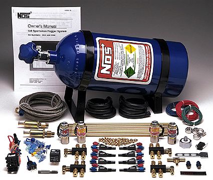
This NOS kit contains all the hardware necessary for an inline fuel injected, six cylinder engine. It's a system, meaning that it injects both fuel and nitrous through the patented NOS nozzles. Included are all hoses, lines, nozzles, distribution blocks, solenoids, filters, connectors and switches. The standard with a 10 lb. nitrous bottle. This standard bottle was used in the installation. It can, however, be ordered with either a 15 lb. or a 20 lb. nitrous bottle. These larger bottle sizes can be specified by adding a suffix to the part number.
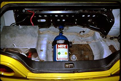
To begin, the location and orientation of the NOS nitrous bottle had to be determined. It was decided that the trunk would provide the best location, but the bottle had to be mounted so that the siphon tube would be at the back of the bottle. This is necessary because the liquid N2O will be forced to the back of the bottle during vehicle acceleration. When installed, the bottle should have its valve handle pointed toward the front of the vehicle, with the NOS bottle label facing "up". The bottle bracket was secured using 5/16" or No. 12 sheet metal screws.
Next, the main nitrous feed line was installed from the trunk to the engine bay. It's easiest to route this line following either the main fuel line or the brake lines under the vehicle. One-half inch Tinnerman clamps or nylon tie-wraps could be used to securely support the nitrous line. A hole must be drilled through the trunk, under the vehicle, to gain access to the nitrous bottle.
At this point, it's a good idea to disconnect the Negative ground terminal from the battery to avoid any unpleasant surprises.
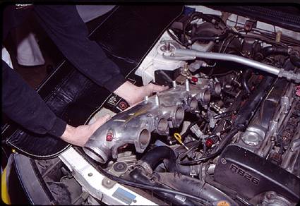
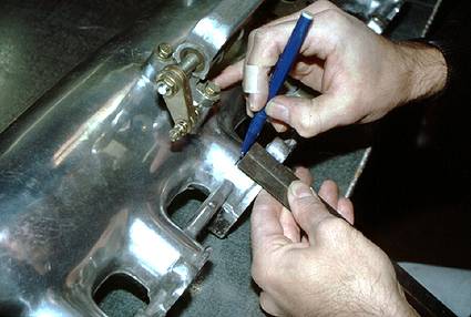
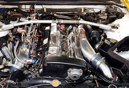
Prior to removing the intake manifold for installation of the Fogger™ nozzles, mark on the manifold the desired nozzle locations. These should be located approximately one inch (1") from the cylinder head. Make sure that there is adequate clearance for the nozzles, lines, fittings and distribution block.
Remove the intake manifold and retain all hardware for re-installation. Remember to use new gaskets when re-installing. Take precautions such as covering the intake ports to prevent any debris from entering the engine. A clean engine is a happy engine. Refer to the manufacturer's service manual for sequence and torquing of manifold bolts.
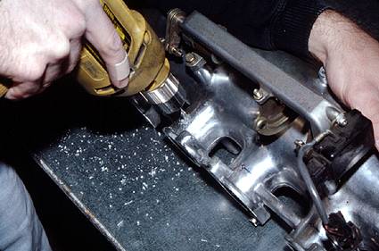
Once more, measure and verify the intake manifold location where you intend to install each nozzle. All holes drilled should be perpendicular to their respective intake runner. Carefully drill a ¼" diameter hole for each nozzle. If possible, drill the holes so that they all line up straight on the manifold.
Use a 1/16" NPT tap on each hole. Because this is a pipe thread, be careful not to run the tap too deep into the manifold runner hole as this may prevent the nozzles from adequately sealing. The goal here is to have the discharge orifice of the nozzle clear the sealing of the runner to assure that the nitrous is being properly distributed. After the drilling and tapping has been completed, clean the manifold thoroughly and remove all debris.
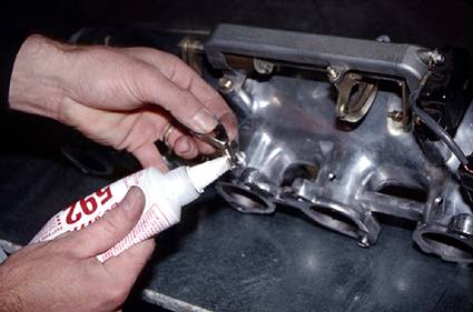
Apply Teflon paste to the nozzle threads before installing them in the manifold. This is to avoid the possibility of any vacuum leaks from occurring. Teflon® tape should not be used because it requires relatively more torque to properly seal. This could cause damage to the NOS fittings and nozzles. Teflon could also break loose and become lodged in the nitrous or fuel solenoids, or solenoid filters. This can cause engine damage or failure.
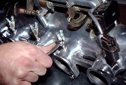
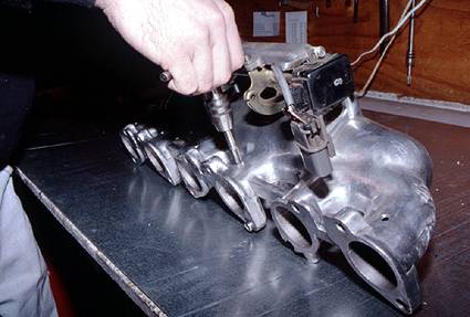
Install a NOS nozzle into each of the ¼" manifold runner holes. Orient them so that each discharge orifice is pointed down the intake manifold port, toward the cylinder head intake valve. The discharge nozzle orifice needs to clear the roof of the intake runner by about 1/8". Be careful not to over-torque the nozzles.
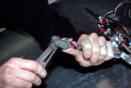
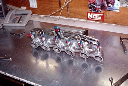
Now is the time for bending the hard lines to connect the nozzles to their respective distribution blocks. A tube-bending tool, available under NOS P/N 15991NOS, is required for this work. Use all the fittings provided and be aware that NOS has color-coded the nitrous lines so that "red" is for fuel and "blue" represents nitrous. Nitrous nozzle feed lines should be bent and plumbed so that they are in line with each distribution block.

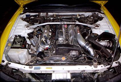
Re-install the intake manifold, using all hardware that was retained during its removal. Be sure to use a new intake manifold gasket. Re-attach all lines, electronics and any other parts that were removed or disconnected during the intake manifold removal process.

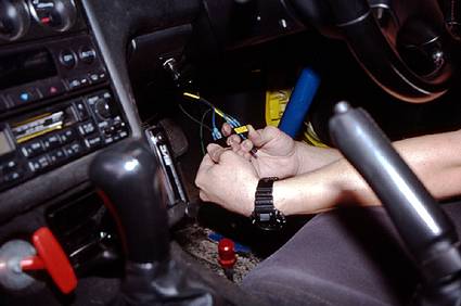
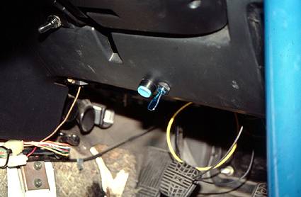
The next step is to tap into the fuse box for an ignition-activated power source for the toggle switch that is used to "arm" the nitrous system. This switch can be installed at a location on the dash that is convenient to the driver. Activating this switch puts the nitrous system into a "standby" mode. The system itself won't actually function until the engine is at wide open throttle . This condition is confirmed by a microswitch that is installed on the throttle body.
The purge valve can be installed at this time. This valve is activated to expel or purge the nitrous lines prior to use, for more consistent performance. This procedure is good insurance that the nitrous lines are free of air and/or gaseous nitrous that could hinder or compromise performance. Be sure that the purge line is aimed away from the motor. A good idea is to have the purge line aimed so that it will shoot up and over the windshield.
The last installation step is to plumb an additional source of fuel to the fuel solenoid. Fortunately, the Skyline had an extra ¼" NPT tap on the O.E. fuel rail, this was used as a fuel source. More fuel is required when using a nitrous system because a lean condition will otherwise result.
This completed the installation. Prior to actual vehicle testing, the lines and fittings were all given a good visual once-over, to assure that there were no leaks. As mentioned earlier, this car is being set up for IDRC and NIRA drag racing. A lot has yet to be done, including additional testing and tuning. We'll keep you informed on the progress.